Cable Modem
+The Modem
Configuration
Surfboard
LED's
+Cable
Stuff
Cable Network
CMTS and UBR's
Head-end
+ISP
Blueyonder
+Network
DHCP/
IP address
Network Card
Caches/Proxies
Trace
Route
Docsis
Ping
+What
Else?
Installation
Speeds
USB
+Related
Info
Getting a new PC?
Internet
Sharing
Glossary
Security
Links
FAQ
The Cable Network
Your cable modem will connect to a cable network, often called CATV ( Cable TV ) or technically known as HFC/RF ( Hybrid Fibre Coaxiel/Radio Frequency ). You may also use a cable network for cable TV. The network is made up of coaxiel and fibre optic cable.
This may look confusing but once you have read it, you should easily understand how
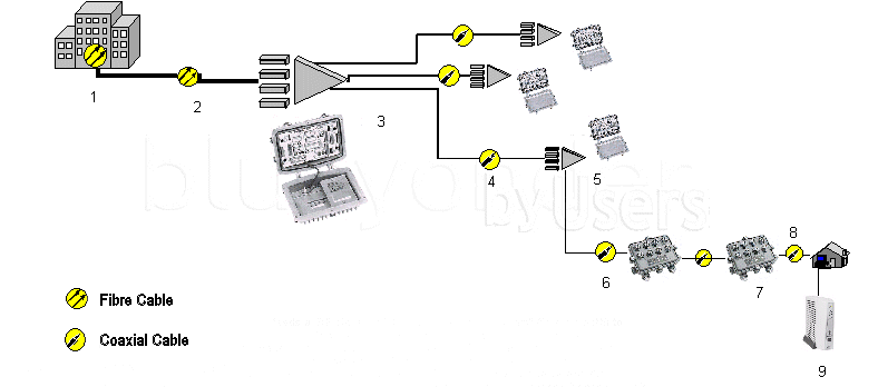
Here is a diagram of Telewest's
( Blueyonder ) cable
network ( click to enlarge ):
Note: HSI stands for Hi-Speed
Internet ( cable modem )

Courtesy
of By-Users
1. Head-End - This is where the UBR sits. The UBR feeds an RF signal of 331Mhz on the "downstream" (forward path) to the fibre optic laser. The laser converts the RF signal to light for onward transmission to the fibre node in the street.
2. This the fibre optic cable that runs from the Head-End to the main street fibre node cabinet. There are two separate fibres on this, run one for the downstream (forward) and one for the upstream (return). This length of cable can vary from 1-25km!
3. This is the street-side fibre node. It converts the fibre optic light signal back to RF for the forward path (which then travels towards the home) and from RF to fibre optic light for the return path (which travels back to the Head-End). These cabinets are usually noticeable by their large double doors.
4. This is now the RF distribution cable which carries both RF signal, forward and reverse, between the various amplifiers in the street. The distance of cable can range from 50-500m in length.
5. This is the RF distribution amplifier. Depending on how big the geographical area is, you may see 2-3 of these in a "daisy"chain effect. Some feed other amplifiers (cascade amps) and some feed the customers(distribution). They are usually housed in the smaller green/grey cabinets or may be underground.
6. This is again part of the RF cable network. The purpose of this cable is to take the signal from the amplifier and feed it to various TAPs(Terminal Access Point) (7). These cables pass both the forward and return signal and can range in length from 10-200m.
7. This the TAP. It can serve 2,4 or 8 customers with RF signal. Older areas can have a "STARTAP" system which is a single unit that can feed many more customers but this is a variant of the same idea. The TAPs again serve forward and return with the customer "drop" cable that is attached to them
8. This the customer "drop" cable. This is the cable that is installed from the pavement outside to the internal customer premises. It can range from 10-100m. When it is inside it can be split to serve different services (Digital, HSI etc).
Hosted
By
![]()
Partners:
325i Scotland

Best Viewed in IE 5.5+ at 1024 x 768 - Webmaster: Nick Jones